Conrad Bock
Reprinted from
Journal Of Object-Oriented Programming
Vol 12, No 4, July/August 1999
Copyright © 1999
SIG Publications, Inc, New York, NY
Control Flow |
Data Flow |
State Machine |
? | |
Inputs determined |
At Start |
Before Start |
At Start |
Before Start |
Start conditions |
Internal |
Internal |
External |
External |
The behavior models above can be unified into one, but at the expense of making them more cumbersome to use. The next article addresses this topic.
The same observation applies the three types of behavior model. Each model could be used for all programming tasks. For example, control flow could be used in embedded system applications by defining special steps that wait for external events. However, each model emphasizes certain aspects of behavior and de-emphasizes others, making each more suitable for particular applications. For example, control flow emphasizes the sequencing of steps by requiring one step to finish before another starts. It de-emphasizes the calculation of inputs by using whatever information happens to be available when a step starts, according to some unrestricted algorithm. This makes control flow more suitable for applications in which the exact sequence of steps is most important, as in business applications.
Data flow emphasizes the calculation of inputs by requiring the outputs of one step to be explicitly linked to inputs of another step or steps. It de-emphasizes the sequencing of steps, because the time at which all the inputs to a step arrive is determined by however long the various input steps take to complete. This means some steps may get all their inputs earlier than others in a less restrictive order than control flow. These characteristics make data flow more suitable for applications in which the proper determination of inputs is most important, as in manufacturing applications.
State machines emphasize response to external stimuli by requiring that each step start only when certain events happen in the environment of the system. It de-emphasizes the sequencing of steps by allowing this to be controlled by external events. It also de-emphasizes the calculation of inputs to each step by doing it as part of the steps themselves. This makes state machines more suitable for applications that operate in response to their environment, as in real-time or embedded applications.
Another way to make a behavior model object-oriented is to invoke operations instead of functions in each of its steps. For example, a method written in C can be translated to C++ in part by substituting message-passing for function calls. Likewise, the steps in data flow or state machines can send a message rather than perform a more complicated or non-object-oriented computation. Languages like CLOS and modeling techniques like OOIE make this translation very easy by using the same syntax for function calls and message-passing. In these languages, polymorphism is introduced by statements that are separate from function or operation invocation. None of the code calling a function needs to change when the function is made object-oriented. This facilitates the transition from behavior specifications written by non-computer professionals, like business behavior modelers, to object-oriented implementations [10, 11].
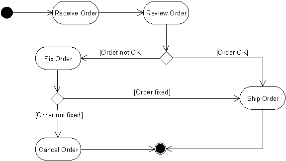
The two simple techniques above can transform a seemingly old-fashioned behavior model into an object-oriented one. For example, the control-flow model in Figure 1 would not be acceptable to an OO practitioner, because it does not relate the steps or the entire behavior to objects responsible for them. This is an incomplete use of the UML activity notation [2].

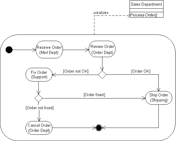
Applying the two techniques produces the model in Figure 2, which is object-oriented. It uses the OOIE convention that the type of object receiving a message is specified in parentheses below the name of the operation that it supports. For example, the operation FIX ORDER is available on the object type CUSTOMER SUPPORT, because supporters are responsible for contacting the customer and helping them correct the order. UML unfortunately does not have a concise notation for this yet. It provides swimlanes, wherein each step is assigned to a column on the diagram corresponding to the type of object responsible for that step. Figure 2 also makes the entire control-flow model into a method by connecting it to the operation it implements, namely the operation PROCESS ORDER on the object SALES DEPARTMENT. UML uses the «realize» dependency to model this, notated by a dashed arrow. These two additions make the model object-oriented by relating the steps and entire behavior to objects that handle them.

In passing it should be mentioned that it is a common mistake to assume messages are passed between steps. For example, in Figure 2 it might be mistakenly taken that when step RECEIVE ORDER is done, it sends a message for REVIEW ORDER to begin. Such an interpretation would impair the reusability of the steps, because a step would imply what others must be executed after it, rather than allowing the sequence of steps to be determined by control-flow links in each diagram where the step is used. A better interpretation is that messages are passed from the method containing the steps to the operation in each step. For example in Figure 2, the method for the PROCESS ORDER operation on the SALES DEPARTMENT object invokes the SHIP ORDER operation on the SHIPPING object. This way the operations invoked by the steps have no dependence on each other. The method containing the steps coordinates the steps by defining their order and the conditions under which they are invoked, without making the operations in them dependent on each other.
An advanced technique to make a behavior model object-oriented is to associate each step with the changes to objects that the step is intended to cause, and associate those changes with the steps that they initiate [12, 13]. For example, Figure 3 shows the effects of fixing a roof, namely, a fixed roof and workers available for another job. Each has their own effect, billing the customer and assigning workers, respectively. The figure uses the UML signal flow notation in activity diagrams to notate the effect of each step. This is unfortunate because it forces the user to employ object flow to model cause and effect. For example, a fixed roof would not necessarily be an input to billing a customer, only the reason for doing so. The UML will be discussed in more detail in the next article on unified behavior models. This technique is not normally applied to data flow, because effects of a step are implicitly modeled in the structure of objects returned for consumption by later steps. When applied to state machines, this technique should not be confused with the events that trigger the beginning of steps in a state machine. State machine events model object changes, but they are caused by external factors, not by a step in the state machine.

In addition to the general techniques described so far, there are a couple techniques that apply to particular kinds of models. Fully object-oriented data flow requires that the data passed between steps are objects of certain types, perhaps also in certain states, rather than unstructured or non-object-oriented data. One of the objects passed to a step is usually used as the target of the step's operation. With these restrictions it becomes object flow.
A fully object-oriented state machine requires that it be associated with a single type of object, and that each step in the machine correspond to a particular configuration of the data in the object. These configurations are called states. For example, a state machine for soda dispenser might have steps for the state of the dispenser being ready to take an order, of having taken in money, of having dispensed soda, and of having given change. A more complete model of states and state machines will be presented in a later article.
[2] Rational Software, et al, UML Semantics, version 1.1, Rational Software Corporation, Santa Clara, CA, September 1997, chapter 11.
[3] Kernighan, B. W. and D. M. Ritchie, The C Programming Language, Prentice Hall, Englewood Cliffs, NJ, 1988.
[4] Martin, J., and J. J. Odell, Object-Oriented Methods: A Foundation (UML edition), Prentice Hall, Englewood Cliffs, NJ, 1998.
[5] Keller, G. and T. Teufel, SAP R/3 Process Oriented Implementation: Iterative Process Prototyping, Addison-Wesley, MA, 1998.
[6] Graham, P., ANSI Common Lisp, Prentice Hall, Englewood Cliffs, NJ, 1996.
[7] Filman, R. E. and D. P. Friedman, Coordinated Computing: Tools and Techniques for Distributed Software, McGraw Hill, New York, NY, 1984, chapter 9.
[8] Harel, D., and M. Politi, Modeling Reactive Systems With Statecharts: The Statemate Approach, McGraw Hill, 1998.
[9] Rational Software, op cit, chapter 4.
[10] Kiczales, G., J. Des Rivieres, and D. Bobrow, The Art of the Metaobject Protocol , MIT Press, 1991.
[12] Martin, op cit, pp 145-148.
[13] Keller, op cit, chapter 4.